Diesel Tailgate

2003-2024
1999-2004 $10/$15/$20 auxiliary idle controller (AIC)
Source:Rob (Rob SSN 23)
This is my second (and last) article to be posted on TheDieselstop.com However, this is the updated version. There are several errors on the TDS copy, but their article editor won't fix them. These mistakes have been there since Sept of 2004.
This modification will allow you to manually set and adjust the idle speed of your 1999-2004 7.3 L PSD without spending $400-600 for the factory AIC. The $15 AIC option will add a indicator light to let you know that the AIC is on. The $20 can only be used with the parking brake set. The 1999+ trucks will high idle automatically during the colder months when the oil is cold, but an AIC is handy for:
- avoiding wet stacking, caused by idling after the post turbo EGT falls below 275 degrees
- getting full power out of the AC during pit stops
- jump starting another vehicle without having to sit in the truck
- impressing your friends with your awesome electrical know-how
It should not be used as a low speed cruise control for safety reasons. None of my AICs will disengage if the brakes are applied. The $20 however can only be turned on when the parking brake is set.
Why you might want to buy the Ford AIC
- It can automatically put your truck into high idle when the parking brake is applied
- It has a digital display
- It will hold an exact RPM. The $10/$15 will vary speed slightly as the engine warms/cools
- It has a warrenty
If you're still with me, here's how to build your own.
WARNING: If your trucks wiring differs from the example or if you're not quite sure what you're doing, DO NOT do this mod. You can damage your truck, which is more costly than buying a factory AIC. Double check your wiring and be sure to not short any wires while the truck is running.
$10 AIC procedure
Time required
About 1-2 hoursItems needed:
- R1 potentiometer with linear taper (see Table 1 for values)
- R2 potentiometer with linear taper (see Table 1 for values)
- 2 knobs for above potentiometers
- Double pole, single throw (DPST) switch
- 16 guage wires (4 colors: red, green, brown, grey)
- Electrical tape
- Heat shrink tubing
| 1999-2002 7.3 L | 2003 7.3 L | 2003 6.0 L | 2004 6.0 L | |
| R1 | 5K | 50K | ? | ? |
| R2 | 5K | 10K | ? | ? |
Tools required:
- multi-meter
- slot screwdriver
- wire strippers
- Soldering iron and solder
- adjustable wrench
- allen key
- lighter
- hack saw
- drill, dremel tool, etc as required to mount controls
Figure 1
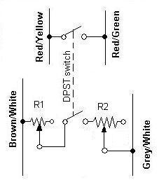
$10 AIC diagram
- Locate the accelerator pedal and remove the 3 fasteners to remove it.
- Locate the wires with the following colors in the wiring harness connected to the pedal: (see photo 1)
- Red w/ yellow tracer
- Red w/ green tracer
- Brown w/ white tracer
- Grey w/ white tracer
- Strip and solder approximately 2' (or more depending on where you want to mount the controls) of the following wires to the above wires:
- Yellow
- Green
- Brown
- Grey
- Connect the yellow and green leads to one pole of the DPST switch (so that the yellow and green leads are electrically connected when the switch is on). Check with the multimeter.
- Open fuse panel access cover on the driver's side
- Connect the brown lead to the left terminal of the R1 potentiometer. Connect more brown wire to the center terminal of the R1 potentiometer.
- Cut off excess post on the R1 potentiometer and mount it behind the fuse panel access cover. Install the knob with an allen key.
- Connect the brown lead from the center of the R1 potentiometer to the other pole of the DPST switch.
- Run a grey lead from the last terminal of the DPST switch to the left terminal of the R2 potentiometer.
- Connect the grey lead from the accelerator pedal to the center terminal of the R2 potentiometer.
- Ensure that all connections are not grounded or touching.
- With the mulimeter, set the R1 potentiometer to half and the R2 potentiometer to 0 ohms.
- Set the DPST switch to off.
Test and Tune
Start the truck and allow to idle for 1 min. Flip the DPST switch to on. Adjust the R1 potentiometeruntil idle speed is approximately 1100-1200 rpm. The full range of the R2 potentiometer should change the idle speed ~ 100 rpm. Once you are satisfied with the idle speed and range of adjustment, tape down the knob on the R1 potentiometer (to avoid accidently changing the setting). Flip the DPST to off. Idle speed should return to 600-700 rpm.
final installation
- Mount the DPST switch and R2 potentiometer as desired. (see photo 3)
- Reinstall accelerator pedal
- Heat shrink and/or tape all electrical connections and zip tie loose wires
- Reinstall fuse panel access cover
- Grab a cold one and admire your work
- Take a picture of your install and email it to me!
$15 AIC procedure
This version adds an LED indicator that lights up with the AIC is in use.
Extra items for $15 AIC:
- LED and holder
- 1N4004 Diode
- 680 ohm resistor (1/2 watt)
- 16 guage wire (red, black)
Figure 2
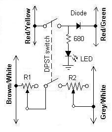
$15 AIC diagram
- Follow steps 1-13 of the $10 AIC procedure.
- Cut the green lead wire 1-2" from the DPST switch.
- Solder the red lead and the anode (+) of the diode to the green lead coming from the DPST switch.
- Solder the Cathode (-) of the diode to the remaining green lead.
- Solder the red lead to 680 ohm resistor
- Solder the resistor to the (+) terminal of the LED
- Solder the black wire to the (-) terminal of the LED
- Connect this black lead to ground
- Test and tune per $10 AIC
- Use the LED holder to mount the LED during the final installation phase.
$20 AIC procedure
NOTE: do NOT build to this procedure yet. It's not finished.
This version enhances the $15 model by only allowing the AIC to operate when the parking brake is set. Just be sure to have it switched off when you start your truck. This is the same circuit as before except that the SPST switch activates the 2 relays only when the parking brake is set.
Extra items for $20 AIC:
- 30 Amp automotive relays (qty 2)
- Single pole single throw (SPST) switch
- more 16 guage wire (red, black)
stuff from the $15 AIC that you won't need:
- - 1N4004 Diode
- - DPST switch
Figure 3
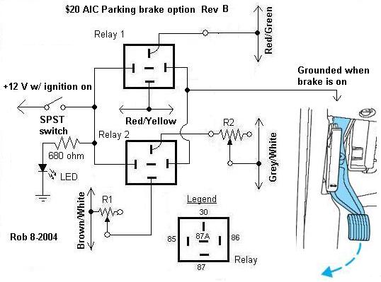
I need a bit of help figuring out which wire to tap into on the E-brake. Please send me the info if you know.
- Follow steps 1-3 of the $10 AIC procedure.
- Connect the yellow lead to pole 87 of Relay 1.
- Connect the green lead to pole 30 of Relay 1.
- Follow steps 5-7 of the $10 AIC procedure.
- Connect the brown lead from the center of the R1 potentiometer to pole 87 of Relay 2.
- Run a grey lead from pole 30 of relay 2 to the left terminal of the R2 potentiometer.
- follow step 10 of the $10 AIC procedure.
- Connect black leads from terminal 86 on both relays to the white wire that's grounded when the brake is set.
- Connect a red lead to a +12V with ignition on. Connect this to one pole of the SPST switch.
- From the other pole of the switch, run 3 red wires. 1 goes to the 680 ohm resistor and 2 go to pole 85 of relays 1 and 2.
- Follow steps 5-10 of the $15 AIC procedure.
Photos
Click all to enlarge
Picture 1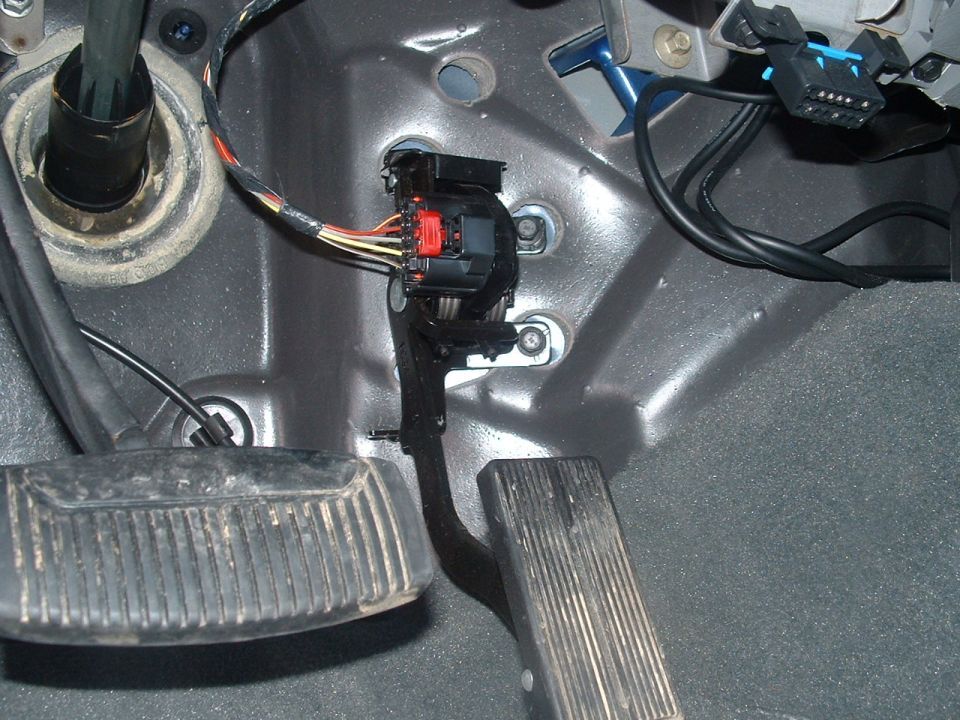 |
Wires: Red w/ Yellow Red w/ green Grey w/ white yellow - not used for this mod Brown w/ white |
Picture 2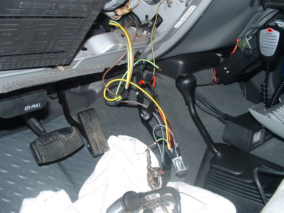 |
The diode is about to be soldered into the green wire. You can see the R1 potentiometer (already taped down) on the metal rail at the bottom of the fuse panel. |
Picture 3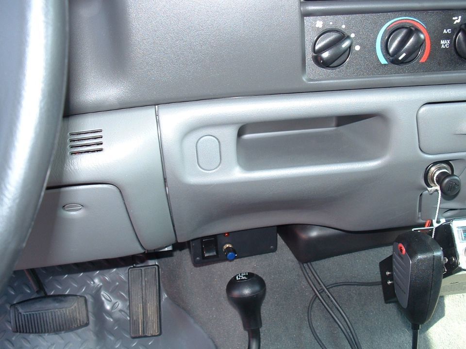
|
For my final installation, I mounted all the hardware in a project box. It could also be dash mounted. |
Glossary
- Wet Stacking = occurs in diesel engines run with little or no load for an extended period of time. Cylinder walls become cold and unburnt fuel will accumulate on them. This will cause damage if done often enough.
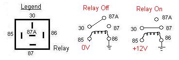
- Relay = electrically actuated switch. Automotive relays typically have 5 terminals: 30, 85, 86, 87 and 87a. When a small amount of current flows between terminals 85 and 86 (in either direction), it causes the connection between terminal 30 and 87a to break and connects 30 and 87. See below: Relays allow you to turn on high current items (e.g. amplifiers or exterior lighting) with a small, low current wire rather than running a high wire into the cab. They also allow you to turn on many seperate things with one switch. Neat things can happen when you connect many relays or use the off position from one to turn another on.
Thanks to DixieDiesel for the idea.
Comments, suggestions, or questions about this site? Email Rob at ![]() .
.
This site is optimized for Google Chrome.
Diesel Tailgate: Get Big! TM